Measure Command
The Measure command allows you to measure a distance between two points in your simulation. Each individual measure can be shown in millimeters, centimeters, or meters regardless of the others measures.
The Measure command is useful if you wish to quickly have an idea of a distance between two points in your simulation.
The Measure command can be accessed from the default Tools sub menu:

Measure
Upon activating this command, aim the controller's laser and press the trigger to set the starting point of the measure. Then, aim the laser at the second point of the measure and press the trigger. A measure tag will be spawned between the two points, displaying the distance seprarating them.
This measure tag is collaborative: your collaborators will see it.
While the Measure Command is activated, you can create as many measures as you want. The created measures will remain upon exiting the command.
You can move a measure tag anywhere in space using by clicking on the label button once inside the command. This will not change the two points between which the measure was made, but rather allows you to replace a measure tag to make it more visible.
Each measure tag can be grabbed and moved to a measure's side.
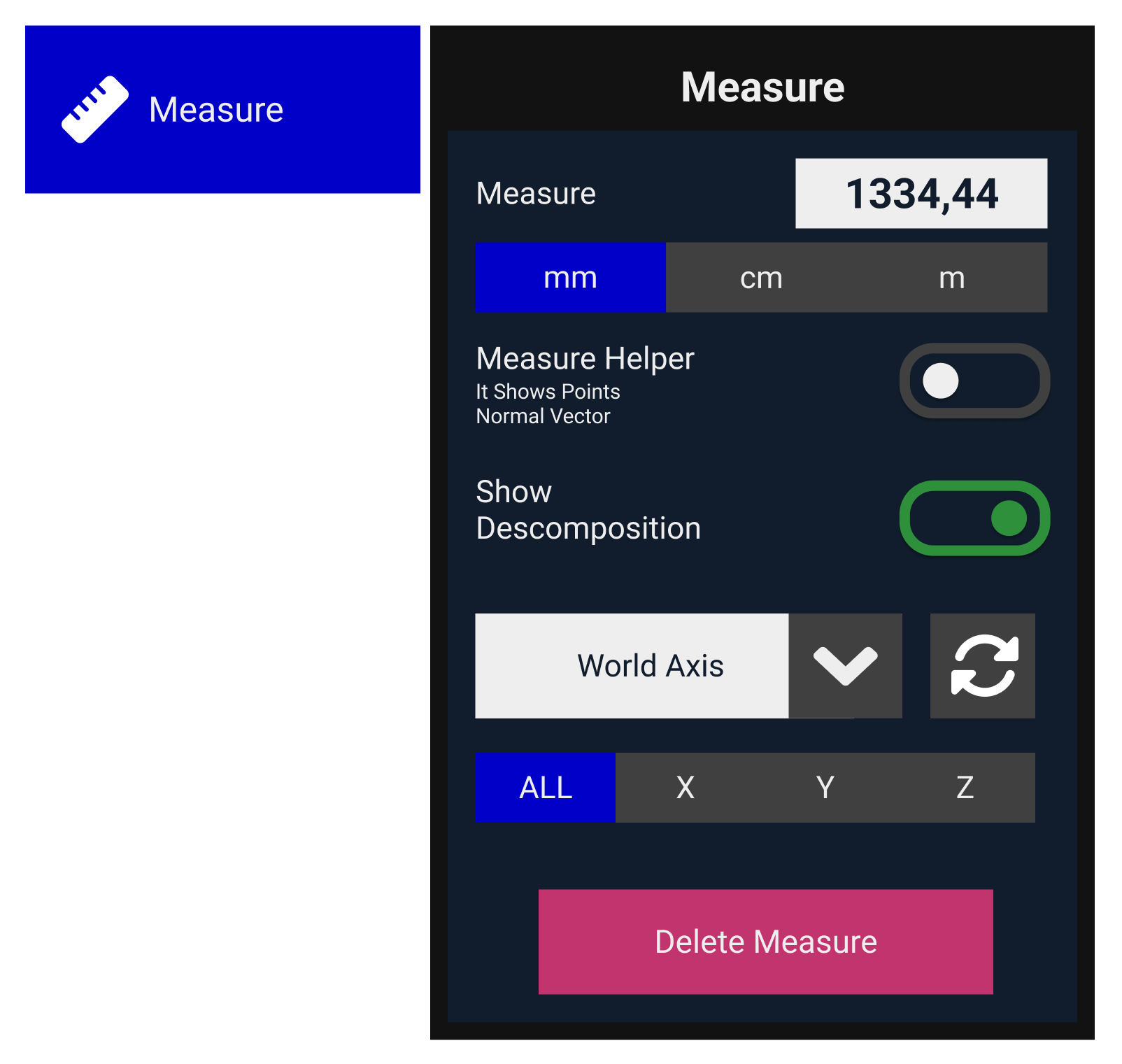
The bracelet will also show the measure distance as all of its options:

Measure Helper
When active, a straight line from each object's normal surface will show in the scene. This line serves just as a helper to display a normal line, and it doesn't calculate any distance. To calculate a distance from one point, we recommend using the Laser Command
Show Decomposition
This option will activate measurement decomposition in all three axes. By default, it will consider the scene's world axis as the baseline and use the X-axis as the starting point for decomposition. Users can change the axis baseline from the combo box. The buttons next to the combo box provide the option to display different positions of the decomposition or even visualize just one axis.
World Axis: Baseline axis of the decomposition will be scene's oriented axis
Source Axis: Baseline axis of the decomposition will be the Source object axis
Target Axis: Baseline axis of the decomposition will be the Target object axis
Normal Axis: Is a decomposition based on the source point normal as X axis and "world up" as Z axis (Y is computed to create a valid base)
Video Example
Other Measures Commands
You can select the full pie menu to show two additional measure commands
Minimal Distance
Minimal distance command allows users to select any two objects in the scene, and Skyreal VR will detect the closest point between them to display its distance. To do so, Skyreal VR uses object's convex decomposition, so its accuracy will depend on this.
Laser
When using the laser option, user can create a point on any surface that will ray-cast a line using surface's normal line. The measure indicated in the label will dynamically change during runtime according to laser's target.
Custom Parameters
Use Collaborative Color: Check this to make the measure line use the user's collaborative color
Measure Color: Set the color of the measure line (if Use Collaborative Color is unchecked)
Measure Thickness: Define the thickness of the measure line (in meters)
Move After Click: Check this to make the mesure line moveable after it has been created